
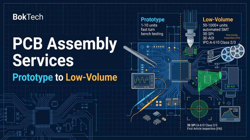
Quick Takeaway (TL;DR): Rapid prototyping and low-volume printed circuit board assembly (PCBA) operate on identical high-speed SMT machinery, but they pursue fundamentally opposite engineering objectives. A prototype build (1 to 10 boards) optimizes for speed, bench debugging flexibility, and rapid design validation; a low-volume production run (50 to 1,000+ boards) optimizes for process repeatability, statistical yields, IPC-A-610 Class 2/3 compliance, and supply-chain traceability. Treating a low-volume run as an informal prototype results in unrecorded component substitutions, assembly voids, and uncontainable field failures. Scaling successfully requires locking a synchronized data package (Gerber, BOM with approved alternates, centroid CPL), establishing a tiered inspection protocol (3D SPI, 3D AOI, 3D AXI for hidden joints), defining formal First-Article Inspection (FAI) sign-off, and capturing lot-level component traceability before production begins.
1. The Core Paradigm Shift: Proving Design vs. Proving Process
The transition from engineering prototype to commercial pilot run represents a shift in risk management:
| Operational Dimension | Prototype Assembly (1 to 10 Units) | Low-Volume Production (50 to 1,000 Units) | Failure Risk When Scaling Unprepared |
| Primary Objective | Validate schematic logic and functional firmware | Prove process capability, thermal reflow profiles, and yield | Batch scrap due to unoptimized SMT thermal mass |
| BOM Status | Fluid; engineering rework and hand wiring tolerated | Frozen; exact MPNs and approved alternates locked | Production line stoppage caused by allocated single-source ICs |
| SMT Tooling & Setup | Frameless stencils; manual visual feeder loading | Framed laser-cut stencils; optimized feeder mapping | Solder paste volume inconsistency; component pick errors |
| Inspection Rigor | Visual inspection + sample X-ray on dense BGAs | 100% 3D SPI + 100% 3D AOI + AXI on all hidden joints | Latent solder bridging and Head-in-Pillow (HiP) defects |
| Workmanship Standard | Functional bench acceptance ("It powers on") | Strict IPC-A-610 Class 2 or Class 3 conformance | Customer rejection during incoming quality control (IQC) |
| Traceability Depth | Basic (Engineer's lab notes) | Unit-level 2D barcode serialization + component lot tracking | Inability to isolate component defect batches during field recalls |
Explore our dedicated low-volume PCB assembly capability for detailed production parameters, and consult our PCB manufacturing services for bare-board fabrication options.
2. Sourcing Model Strategy: Turnkey vs. Consigned vs. Hybrid
Choosing who procures components dictates lead times, cash flow, and factory accountability. As order volume increases, sourcing models must transition away from informal purchasing toward structured supply-chain channels.
Full Turnkey Sourcing (Recommended for Scaling)
The assembly facility procures 100% of the bill of materials directly from authorized global distributors (Mouser, Digi-Key, Arrow, Element14) and verified factory direct channels.
•Advantages: Eliminates international shipping duties and customs clearance delays; aligns bare-board fabrication with component arrival; places full accountability for component authenticity and shortage buffers on the manufacturer.
•Factory Requirement: The BOM must include exact Manufacturer Part Numbers (MPNs) and at least 1 to 2 pre-approved alternates for passive components and discrete semiconductors.
Consigned (Kitted) Sourcing
The customer procures, kits, and delivers all components to the assembly plant.
•When It Applies: Essential when using pre-programmed proprietary ASICs, custom enclosures, or components allocated specifically to the customer's corporate procurement account.
•Strict SMT Packaging Rules: SMT pick-and-place feeders cannot load loose parts or short cut-tapes. Consigned components must be supplied in continuous tape with minimum 12-inch (300mm) tape leaders and trailers, or in original manufacturer reels and JEDEC matrix trays.
•Attrition Buffers: Consigned orders must include component overage buffers (typically 3% to 5% for standard passives, minimum 1 to 2 extra ICs) to account for SMT feeder setup scrap.
Hybrid Sourcing
The practical middle ground: the customer supplies proprietary, pre-programmed, or long-lead ICs, while the manufacturing partner procures standard passives, inductors, connectors, and commodity logic.
| Sourcing Model | Procurement Control | Lead-Time & Customs Risk | Component Attrition Liability | Optimal Production Stage |
| Full Turnkey | Low management effort; automated API quoting | Lowest; components clear local customs seamlessly | Handled by manufacturer inventory | Standard prototypes and all production scaling |
| Consigned (Kitted) | 100% customer control over part sourcing | High; customs delays, export controls, kitting errors | Customer must provide 3%–5% extra overage | Pre-production validation using existing inventory |
| Hybrid Sourcing | Balanced; control over critical silicon | Moderate; custom parts must arrive before line scheduling | Split; customer covers custom silicon attrition | Transition from late-stage prototype to volume run |
Review our PCB requirements for manufacturing files to structure your BOM dataset properly.
3. SMT and Mixed-Technology Process Engineering
Low-volume manufacturing requires dedicated tooling and calibrated thermal profiling that rapid prototypes often skip:
Solder Paste Stencil Engineering
•Prototype Stencils: Standard chemically-etched or unmounted stainless steel foils (100 µm to 120 µm) designed for manual or semi-automatic printers.
•Production Step-Down Stencils: High-density mixed-technology boards (e.g., pairing a 0.40mm micro-BGA with heavy power inductors) require laser-cut, electro-polished step-down stencils. Stepping the foil from 130 µm down to 100 µm in the BGA field deposits the exact paste volume required across diverse pad sizes, preventing both bridging and solder starvation.
Thermal Reflow Profiling
A reflow oven thermal profile must be calibrated to the specific thermal mass of the populated board:
•Large ceramic inductors, heavy ground planes, and shield cans absorb substantial thermal energy, heating much slower than lightweight 0201 passives.
•For low-volume production, profiling engineers instrument a non-functional sample board with multiple thermocouple sensors to measure preheat ramp rate (1°C–3°C/s), flux soak time (60–120s @ 150°C–200°C), Time Above Liquidus (TAL: 60–90s @ >217°C for SAC305), and peak temperature (238°C–245°C) across every critical package.
Secondary Through-Hole and Mechanical Assembly
•Through-Hole Processing: Connectors and electrolytic capacitors are processed using automated selective wave soldering or titanium solder pallet carriers, ensuring consistent 100% vertical barrel fill without damaging adjacent surface-mount components.
•Hardware Assembly: Press-fit connectors, thermal gap pads, RF shielding cans, and heatsinks require documented assembly torque limits and calibrated insertion tooling.
| Process Engineering Phase | Rapid Prototype Baseline | Low-Volume Production Standard | Quality Impact on Finished Assembly |
| Stencil Architecture | Flat laser-cut foil; manual alignment | Framed, electro-polished step stencil with fiducials | Eliminates solder paste height and area variation |
| Solder Paste Printing | Visual inspection of first print | 100% in-line 3D Solder Paste Inspection (SPI) | Catches 70%+ of SMT soldering defects prior to reflow |
| Reflow Thermal Profiling | Generic standard SAC305 profile | Validated thermocouple profile matched to thermal mass | Prevents component thermal shock and cold solder joints |
| Through-Hole Soldering | Manual hand iron soldering | Automated selective wave soldering or wave pallets | Guarantees IPC Class 2/3 vertical barrel fill (> 75%) |
Consult our guide on PCBA specification: assembly tolerances and acceptance criteria to evaluate placement and solder criteria.
4. Scaled Quality Assurance: Multi-Stage Inspection & Test Architecture
A five-board prototype run can be manually verified on an engineer's workbench with a multimeter and oscilloscope. A 500-board production run requires automated, non-destructive inspection gates:
| Quality Verification Gate | Inspection Technology | Primary Defects Detected | Prototype Phase Scope | Low-Volume Production Scope |
| 1. 3D SPI | Optical phase-shift profilometry | Paste volume, height, area, bridging, smear | Sample check on fine-pitch | 100% automated in-line verification |
| 2. Post-Reflow 3D AOI | Multi-angle telecentric cameras | Bridging, tombstoning, polarity, lifted leads | Recommended | 100% automated inspection |
| 3. 3D Automated X-Ray (AXI) | High-resolution micro-focus X-ray | BGA voiding (< 15%), Head-in-Pillow, QFN opens | Sample check on first board | Sample or 100% on area-array parts |
| 4. Flying Probe Test (FPT) | Moving needle electrical test | Net continuity, component values, shorts | As needed for unpowered boards | Full net verification (up to 200 pcs) |
| 5. Bed-of-Nails ICT | Spring-loaded contact probe fixture | Instantaneous node-by-node electrical test | Not cost-effective | Standard for high-run low-volume (NRE fixture) |
| 6. Functional Testing (FCT) | Custom test jig + firmware execution | Complete operational hardware validation | Manual bench validation | Automated test sequence with logged results |
See our equipment and inspection capabilities to review the verification systems active on our production floors.
5. The Handoff Protocol: 6 Gates Before Scaling Up
Before transitioning a design from prototype status to a low-volume production order, verify your documentation against the following six engineering gates: Prototype to Production Verification Gates: Design Freeze & Revision Synchronization (Artwork = BOM = Centroid = Drawing) Sourcing Verification & Alternate Component Authorization Written Acceptance Thresholds (IPC-A-610 Class 2 or Class 3) Formal First-Article Inspection (FAI) Protocol Sign-Off Production Test Strategy (ICT / FCT Test Fixture Documentation) Environmental & Packaging Specifications (MSL Controls & Anti-Static Packaging) Code
1. Design Freeze and Revision Synchronization: Prototypes generate hardware bug fixes (e.g., cutting a trace, swapping an SMT resistor value, adding a fly-wire). Ensure every physical fix is captured in the CAD layout, generating a synchronized revision package (e.g., Gerber Rev B, BOM Rev B, Centroid Rev B).
2. BOM Scrubbing and Second-Sourcing: Verify that every line item has an active lifecycle status. Replace end-of-life (EOL), obsolete, or single-source parts with active components, and document pin-compatible alternates directly in the BOM.
3. Formal Workmanship Classification: Explicitly state the governing acceptance standard on the assembly drawing (e.g., "Manufacture and inspect to IPC-A-610 Class 2 commercial standards" or "IPC-A-610 Class 3 mission-critical standards").
4. First-Article Inspection (FAI) Agreement: Require the manufacturer to assemble and verify a First Article before releasing the remaining batch. The FAI report must validate component values, polarities, 3D SPI paste volume distribution, and radiographic BGA voiding images.
5. Test Strategy and Fixture Finalization: Transition manual bench testing to an automated Functional Test (FCT) fixture. Provide the factory with detailed test procedures, input power parameters, firmware flashing tools, and clear pass/fail criteria.
6. Packaging and MSL Definition: Specify electrostatic discharge (ESD) shielding bags, partitioned anti-static bubble packaging, and moisture-barrier bags with fresh desiccant for moisture-sensitive assemblies.
6. Traceability, Serialization, and Defect Containment
In rapid prototyping, traceability is rarely prioritized. In low-volume production, traceability determines whether a supplier component issue affects a single identifiable batch or forces a total product recall.
Tiered Traceability Frameworks
•Batch-Level Traceability (Standard Baseline): Records the solder paste lot number, stencil serial number, SMT placement line ID, and reflow profile datalog for the entire production work order.
•Unit-Level Serialization: Laser-marks a high-density 2D DataMatrix barcode onto the surface of each individual PCB. The barcode links the board serial number to automated SPI, AOI, and functional test logs.
•Component-Level Traceability: Scans and links component reel lot codes and date codes to specific board serial numbers, allowing instant containment if an active silicon component is recalled by the manufacturer.
Controlled Rework Procedures
The assembly specification must define strict rework boundaries:
•Limit maximum component rework heating cycles (maximum 2 rework attempts per BGA/QFN location).
•Require vacuum desoldering stations and calibrated hot-air rework profiles to prevent pad lifting and localized PCB substrate delamination.
•Mandate that all reworked units undergo 100% re-inspection via 3D AXI and functional testing.
7. Frequently Asked Questions (FAQ)
Why is consigned assembly often more expensive and slower than full turnkey for low volumes?
Consignment shifts supply-chain logistics onto the customer. Customers frequently supply cut-tape components without required 12-inch leaders, deliver loose parts in mixed bags, or omit component attrition buffers. This forces assembly technicians to manually splice tapes, re-reel parts, or halt automated lines due to component pick errors. Turnkey sourcing eliminates these delays because parts arrive factory-packed in automated reels.
What component overage (attrition buffer) is required for automated SMT lines?
Automated SMT pick-and-place feeders require extra components to thread through tape sprockets and feeder gates. For low-volume builds, standard attrition guidelines require:
•0201 / 0402 Passives: Minimum 50 to 100 extra parts (or 5% overage).
•0603 / 0805 Passives & Discrete Semiconductors: Minimum 10 to 20 extra parts (or 3% overage).
•Expensive ICs, BGAs, and Connectors: Minimum 1 to 2 extra parts (or 1% to 2% overage).
How does a First-Article Inspection (FAI) protect low-volume production yields?
An FAI report validates machine setup before batch assembly begins. The SMT line pauses after the first board passes reflow. Technicians verify component placement, orientation, solder joint wetting, and radiographic BGA voiding against the golden design package. Correcting an inverted diode or incorrect resistor value on unit one prevents scrapping an entire 500-unit batch.
When should a hardware team transition from flying probe testing to a bed-of-nails ICT fixture?
Flying probe testing is optimal for order quantities between 1 and 100 boards because it requires zero custom tooling investments. However, flying probe test cycles can take 3 to 10 minutes per board. When production batches reach 200 to 500+ units, the initial Non-Recurring Engineering (NRE) tooling cost of a bed-of-nails ICT fixture ($1,500 to $4,000) is fully amortized by slashing per-board test cycle times down to 10 to 20 seconds.
8. From Prototype to Low-Volume Production: Partner with BokTech
Navigating the transition from breadboard validation to reliable, high-yield commercial electronics manufacturing requires an experienced manufacturing partner equipped for both rapid prototyping and scalable production:
•Eliminating SMT defects on 0.35mm–0.50mm micro-BGAs and high-density QFN thermal pads through calibrated reflow profiling.
•Enforcing IPC-A-610 Class 2 and Class 3 workmanship with in-line 3D SPI, multi-angle 3D AOI, and high-resolution 3D AXI verification.
•Providing 100% authentic, traceable component procurement through direct authorized distributor networks.
•Implementing custom ICT and functional test fixtures to guarantee complete electrical compliance before shipping.
BokTech delivers end-to-end turnkey PCB manufacturing, precision SMT assembly, and complete box-build integration operating directly from our state-of-the-art facility in Shenzhen. We provide:
•Seamless Scaling Under One Roof: Transition smoothly from 5-board rapid prototypes to 500-to-10,000+ board production runs without changing manufacturing partners or requalifying tooling.
•Certified Manufacturing Standards: Full compliance with ISO 9001, ISO 13485 (Medical), IATF 16949 (Automotive), and IPC-A-610 Class 2 and Class 3 quality management systems.
•Advanced High-Speed SMT Placement: Automated placement lines supporting 01005 passives, 0.35mm micro-BGAs, Package-on-Package (PoP), and nitrogen-purged 10-zone reflow ovens.
•Comprehensive Verification & Testing: 100% 3D SPI, 3D AOI, 3D AXI radiographic inspection, flying probe testing, and custom bed-of-nails ICT fixture fabrication.
•Free Pre-Production DFM & DFA Reviews: Every project receives an exhaustive engineering audit to eliminate footprint discrepancies, balance thermal reflow mass, and verify component sourcing lifecycles before lines are scheduled.
For startup hardware development insights, consult our comprehensive startup hardware manufacturing guide, review our bare-board fabrication specification guide, and check our frequently asked questions.
Ready to scale your prototype into reliable low-volume production? Upload your Gerber, BOM, and Centroid files for an instant quotation, or contact our engineering team today for a complete DFM and production scaling review.


{{ commentCount }} Comments